 English
 Français
 Deutsch
 euskara
 Русский язык
 Italiano
 Português
 Nederlands
 Polski
 Greek
Greek Lietuva
 Türkçe
 日本語
日本語 한어
한어 中文
中文 தாமில்
 فارسی
فارسی हिंदी
हिंदी Tiếng Việt
 ภาษาไทย
 Pilipino
 Indonesia
 தாமில்
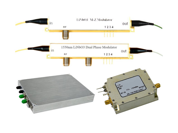
Send us a message
CLOSE
WhatsApp: 15671598018 E-mail: info@SintecLaser.com
![[New Product] Microchip Lasers](/static/upload/image/Stxl30.jpg)
![[New Product] Single Frequency Lasers](https://www.sintec.sg/static/upload/image/1634777782300297.jpg)


")
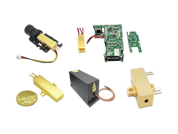
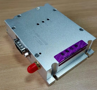
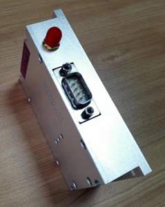
Q-switch drivers are used to drive Q-switches and their frequencies are mainly 24, 27, 41, 68, 80MHz etc.
A high power RF driver module is available in output powers of 50W, 75W or 100W. Powered from 220VAC or 110VAC, the modulation inputs allow either full digital control or activation of an internal pulse generator. First pulse suppression is automatically implemented.
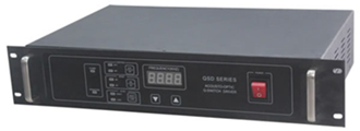 Main Specifications:
RF power output : 50W, 75W or 100W
Frequency: 27.125MHz
VSWR: ≤1.2
Modulation repetition rate: 800Hz-50kHz
First pulse suppression
Modulation control inputs: digital TTL , till 100kHz
Driver over-heat, Q-Switch over-heat
Internal over-temperature protection and over-current protection
Digital display of frequency
Supply voltage input: 220VAC/110VAC, <150W
Dimension: 483x88x308mm
Weight: 8kg
Model Numbers: QSDxxyyZ
QSD - QSD series RF driver
XX - RF frequency, 27-27MHz, 24-24MHz
YY - RF output power (W), 50-50W, 75-75W
Z - others, Z or T
Example QSD-2720T (20W), QSD-2750T (50W), QSD-2775T (75W) or QSD-27100Z (100W)
Main Features of QSDxxyyT Series Digital Q-switch Drivers:
Newly designed digital RF driver has the following features comparing with analog version:
Touch panel,
Digital circuit to improve control accuracy with frequency resolution of 0.01Hz (0.001Hz or less upon request)
Internal trigger synchronizing with laser, to achieve perfect marking
Integrated open load protection
Easier and more accurate panel controlled laser delay.
Other power levels are available upon request.
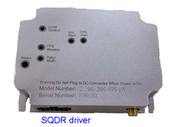
SQDRxxx-yyDC-zzz-aaa series RF drivers are similar to QC0xx-yyDC-zzz drivers but cheaper.
xxx is operation frequency (xxx=041 means 40.68MHz and xxx=080 means 80MHz), yy is maximum output RF power (yy=20 means 20W), D means digital modulation, C means compact size, zzz means operation mode (FPS, PPK, A05 or A05, FPS is default. For more information), aaa is input voltage (aaa=15V means input voltage is 15VDC).
The outline dimension is 95x70x25mm.
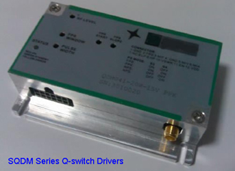
SQDMxxx-yyW-aaV-zzz series RF drivers are similar to QCxxx-yyDC-zzz drivers but cheaper. Their outlines are similar too.
xxx is operation frequency in MHz (xxx=041 means 40.68MHz and xxx=080 means 80MHz), yy is maximum output RF power (yy=20 means 20W), aa means input voltage (aa=15 means 15VDC input, zzz means operation mode (FPS, PPK, RPS or APS, PPK is default. For more information). For example, SQDM041-20W-15V-PPK means operation frequency 40.68MHz, output RF power 20W, input voltage 15V and operation mode PPK.. The outline dimensions are 95x70x25mm.
| Part number | STL-LD832 | STL-LD882 |
| Output Frequency | 80MHz,±0.01% (100ppm) | 80MHz,±0.01% (100ppm) |
| Output Power | >15.0W @50Ω | >15.0W @50Ω |
| Modulation Input | TTL, 1Hz to 1.2MHz | TTL, 1Hz to 1.2MHz |
| Sync Out Level | 3.3V ±5% | 3.3V ±5% |
| Supply Voltage | +12V ±5% | +24V ±5% |
| Supply Current | <2.20A | <2.20A |
| Spurious Levels | -50dBc Maximum | -50dBc Maximum |
| Harmonic Distortion | -20dB Maximum | -20dB Maximum |
| Extinction Ratio | 40dB Maximum | 40dB Maximum |
| RF Rise Time 10% to 90% | <25ns | <25ns |
| RF Fall Time 90% to 10% | <25ns | <25ns |
| Operation Temperature | +10oC to +50 oC | +10oC to +50 oC |
| Storage Temperature | -20 oC to +85 oC | -20 oC to +85 oC |
| Dimension | 103.8x84.1x25mm | 103.8x84.1x25mm |
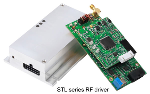
There are 5 potential meters to change the settings as follows:
Prf: setting the RF output power
Pulse Width: setting the pulse width of TTL_Fixed selection with the range 0.8us~25us±10%
FPS Window: FPS window time and its range is 20us~350us±10%
FPS Slope: setting the FPS slope
FPS Start:setting FPS starting point
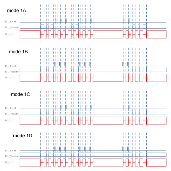
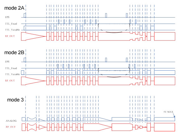
There are 13 RF output modes as follows:
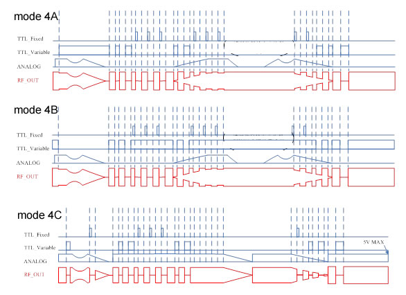
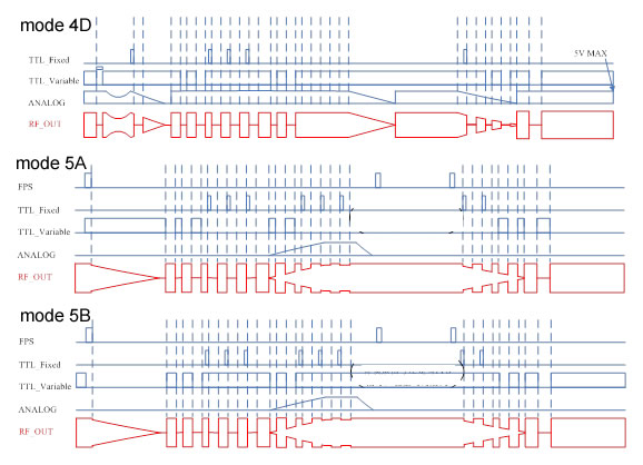
Technical Specifications:
Input electricity: 15~24VDC, ripple £100mV
FPS, TTL_Fixed, TTL_Varibale input resistance 10kΩ±10%
ANALOGinput resistance 10kΩ±10%
FPS, TTL_Fixed, TTL_Varibale low level -0.5~0.8V, high level 2.5~5V
ANALOG input voltage 0~5V
FPS’s input width 1~350uS
TTL_Fixed input range 50ns, period -500ns
TTL_Variable effective input range 500ns, period -500ns
TTL_Fixed output range 0.8us~25us±10%, determined by Pulse Width potential meter
Shortest RF operation time 500ns
Shortest lasing time 500ns
RF fall time <20ns
FPS window range 20~350us±10%
Max. RF output Pmax=20W±10%, max. input electrical power 45W±10%
Adjustable output RF power range 0~Pmax, determined by Prf potential meter
Outline dimension: 100x70x25mm
Part numbers: STZxxx-yyD-zzz
XXX: RF operation frequency, xx=041(40.68MHz) or =80(80MHz)
YY: output RF power (yy=2-20, W)。
ZZZ: first pulse suppression mode (zzz=FPS, TTLF or TTLV)
D: D means digital input modulation, A means analog input modulation
A leading supplier and manufacturer of a wide range of photonics products such as lasers,laser parts & machines.
Office: 18 South Liu Fang Yuan Road, Sintec Industrial Park, Optics Valley of China, Wuhan Hubei, 430205 PR China
Tel: +86 27 51858962
Fax: +86 27 51858989
Whatsapp: 15671598018
E-mail: info@SintecLaser.com