 English
 Français
 Deutsch
 euskara
 Русский язык
 Italiano
 Português
 Nederlands
 Polski
 Greek
Greek Lietuva
 Türkçe
 日本語
日本語 한어
한어 中文
中文 தாமில்
 فارسی
فارسی हिंदी
हिंदी Tiếng Việt
 ภาษาไทย
 Pilipino
 Indonesia
 தாமில்
Send us a message
CLOSE
WhatsApp: 15671598018 E-mail: info@SintecLaser.com
![[New Product] Microchip Lasers](/static/upload/image/Stxl30.jpg)
![[New Product] Single Frequency Lasers](https://www.sintec.sg/static/upload/image/1634777782300297.jpg)


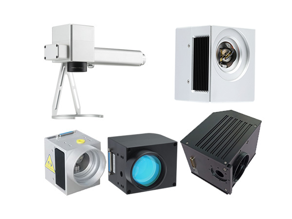
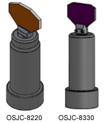 OSJC series galvanometer scanners are designed by adopting the magnet-moving structure, combining the most advanced international photoelectric sensor technology and the PDM control mode, and using the military-grade processes and technologies.
Adopted the photoelectric sensors which imported from America, and owned the proprietary intellectual property rights.
Differential photoelectric sensor for accurate detection of motor rotor position, good linearity, lower drift, high resolution and repeat positioning.
Accurate load design for 10mm mirrors, high accuracy of motor assembly, reasonable structure, very small static friction coefficient and zero offset, all ensured the best dynamic characteristics for the whole system.
Drives with advanced detection ability of position and speed, greatly improved the dynamic response performance and scanning speed of the whole system.
Design of overload, over-current and reverse connect protection, makes the system running more reliable.
The whole system adopted the optimization Designing of electromagnetic compatibility, with high signal-to-noise ratio and strong anti-interference ability.
This scanner system solved the common problems of motor temperature drift, signal interference and zero drift, etc.
| Part number | OSJC-2203 | OSJC-8330 |
| Speed | ||
| Marking Speed (1), mm/s | 7000 | 1000 |
| Positioning Speed, (1), mm/s | 12000 | 1000 |
| Writing Speed (2), (cps) | 520 | 125 |
| Step Response Time(1% of full scale), us | 285 | 940 |
| Step Response Time(10% of full scale), us | 890 | 1500 |
| Tracking Error Time, us | ≤160 | ≤440 |
| Precision and Error | ||
| Linearity | 99.9% | 99.9% |
| Repeatability (RMS), urad | <8 | <8 |
| Gain Error, mrad | <5 | <5 |
| Zero Offset, mrad | <5 | <5 |
| Long-term Drift Over 8 Hours, mrad | <0.5 | <0.5 |
| Scale Drift, ppm/oC | <40 | <40 |
| Zero Drift, urad/ oC | <15 | <15 |
| Scan Mirror Damage Threshold | ||
| K9 Mirror, J/cm^2 | 9.1 | 9.1 |
| Silicone Mirror, J/cm^2 | 10 | 10 |
| Laser Wavelength (3), nm | 10600/1064/355 | 10600/1064/355 |
| Power and Signal | ||
| Input Voltage, VDC | ±15 | ±15 |
| RMS Current, A | 2 | 2 |
| Interface Signal (Digital) | XY2-100 | XY2-100 |
| Interface Signal (Analog), V | ±5 | ±5 |
| Peak Current, A | 8 | 8 |
| Position Signal Input Resistance, kΩ | 10±1% | 10±1% |
| Machinery Scan Angle (4), o | ±15 | ±15 |
| Working Current, Temperature, Dimension | ||
| Working Temperature, oC | 0--45 | 0--45 |
| Storage Temperature, oC | -10--+60 | -10--+60 |
| Suitable Laser Beam Size, mm | 10 | 30 |
| Galvanometer Scanner Dimension (DXL), mm | D22X35.4+D31X17.6 | D38X81.5+D47X20.5 |
| Galvanometer Scanner Weight, g | 120 | 750 |
Note: The above data are tested after 30 min warm-up.
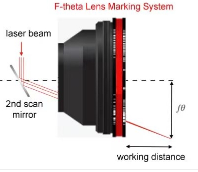
With F-theta objective, F=160mm, marking 2mm height single character
With F-theta objective, F=160mm, marking 1mm height single character per
second Special wavelength coating film can be customized
If any special requirement, customization is available.
| Working Temperature | 0-45℃ |
| Linearity | 99.9% |
| Setting Time | ≤0.8ms |
| Scale Drift | <40PPM/℃ |
| Zero Drift | <15ΩRad./℃ |
| Long-term Drift Over 8 Hours | <0.5mRad |
| RMS Current | 3.5A |
| Peak Current | 20A(Max) |
| Maximum Scan Angle | ±15° |
| Storage Temperature | -10 to +60℃ |
| Resolution | 12Ωrad |
| Repeatability | 8Ωrad |
| Input Aperture | 20.0mm |
| Beam Displacement | 26mm |
| Motor Weight | 280g |
| Frequency | ≤500Hz |
| Input Voltage | ±24VDC | |
Interface Signal | Digital | XY2-100 |
| Analog | ±5V, ±10V | |
| Analog Signal Input Resistance | 200KΩ±1%(Differential input) | |
| Position Signal Input Resistance | 1KΩ±1% | |
| Position Signal Input Scale Factor | 0.33V/° | |
| Position Signal Output Scale Factor | 0.33V/° | |
| Working Temperature | 0-45℃ | |
| Dimension(DXL) | D28X60+D36X19mm | |
| Part Number | OSJC-1105 | OSJC -1403 | OSJC -2206 |
| Input Aperture | 7mm | 9mm | 10mm |
| Linearity | 99.9% | 99.9% | 99.9% |
| Small Step Response Time | 0.3ms | 0.3ms | 0.35ms |
| Maximum Scan Angle | ±15° | ±15° | ±15° |
| Resolution | 12Ωrad | 12Ωrad | 12Ωrad |
| Repeatability | 8Ωrad | 8Ωrad | 8Ωrad |
| Working Temperature | 0-45℃ | 0-45℃ | 0-45℃ |
| Storage Temperature | -10 to +60℃ | -10 to +60℃ | -10 to +60℃ |
| Input Voltage | ±15VDC | ±15VDC | ±15VDC |
| Interface Signal (Digital) | XY2-100 | XY2-100 | XY2-100 |
| Galvo Weight | 45g | 120g | |
| Drive Board Dimension | 75x50x28mm | 75x50x28mm |
| Part Number | OSJC -7106 | OSJC -7110 | OSJC - 7210 |
| Input Aperture | 10mm | 10mm | 10mm |
| Linearity | 99.9% | 99.9% | 99.9% |
| Small Step Response Time | 0.288ms | 0.5ms | 0.3ms |
| Maximum Scan Angle | ±15° | ±15° | ±15° |
| Resolution | 12Ωrad | 12Ωrad | 12Ωrad |
| Repeatability | 8Ωrad | 8Ωrad | 8Ωrad |
| Working Temperature | 0-45℃ | 0-45℃ | 0-45℃ |
| Storage Temperature | -10 to +60℃ | -10 to +60℃ | -10 to +60℃ |
| Input Voltage | ±15VDC | ±15VDC | ±15VDC |
| Interface Signal (Digital) | XY2-100 | XY2-100 | XY2-100 |
| Galvo Weight | 120g | 120g | 220g |
| Driver Board Dimension | 75x50x28mm | 75x50x28mm | 75×50×28mm |
| Part Number | OSJC -7310 | OSJC -2207 | OSJC -2208 |
| Input Aperture | 10mm | 12mm | 14mm |
| Linearity | 99.9% | 99.9% | 99.9% |
| Small Step Response Time | 0.5ms | 0.45ms | 0.6ms |
| Maximum Scan Angle | ±15° | ±15° | ±15° |
| Resolution | 12Ωrad | 12Ωrad | 12Ωrad |
| Repeatability | 8Ωrad | 8Ωrad | 8Ωrad |
| Working Temperature | 0-45℃ | 0-45℃ | 0-45℃ |
| Storage Temperature | -10 to +60℃ | -10 to +60℃ | -10 to +60℃ |
| Input Voltage | ±15VDC | ±15VDC | ±15VDC |
| Interface Signal (Digital) | XY2-100 | XY2-100 | XY2-100 |
| Galvo Weight | 120g | 130g | |
| Drive Board Dimension | 75x50x28mm | 75x50x28mm |
| Part Number | OSJC -2807 | OSJC -2808 | OSJC - 8220 |
| Input Aperture | 16mm | 20mm | 20mm |
| Linearity | 99.9% | 99.9% | 99.9% |
| Small Step Response Time | 1ms | 1.2ms | 0.8ms |
| Maximum Scan Angle | ±15° | ±15° | ±15° |
| Resolution | 12Ωrad | 12Ωrad | 12Ωrad |
| Repeatability | 8Ωrad | 8Ωrad | 8Ωrad |
| Working Temperature | 0-45℃ | 0-45℃ | 0-45℃ |
| Storage Temperature | -10 to +60℃ | -10 to +60℃ | -10 to +60℃ |
| Input Voltage | ±24VDC | ±24VDC | ±24VDC |
| Interface Signal (Digital) | XY2-100 | XY2-100 | XY2-100 |
| Galvo Weight | 280g | 280g | 280g |
| Drive Board Dimension | 90×64×34mm | 90×64×34mm | 80×54×33mm |
| Part Number | OSJC -3808 | OSJC -8330 | OSJC -8250 |
| Input Aperture | 30mm | 30mm | 50mm |
| Linearity | 99.9% | 99.9% | 99.9% |
| Small Step Response Time | 1.6ms | 1.2ms | 2.5ms |
| Maximum Scan Angle | ±15° | ±15° | ±15° |
| Resolution | 12Ωrad | 12Ωrad | 12Ωrad |
| Repeatability | 8Ωrad | 8Ωrad | 8Ωrad |
| Working Temperature | 0-45℃ | 0-45℃ | 0-45℃ |
| Storage Temperature | -10 to +60℃ | -10 to +60℃ | -10 to +60℃ |
| Input Voltage | ±24VDC | ±24VDC | ±24VDC |
| Interface Signal (Digital) | XY2-100 | XY2-100 | XY2-100 |
| Galvo Weight | 750g | ||
| Drive Board Dimension | 90×64×34mm |
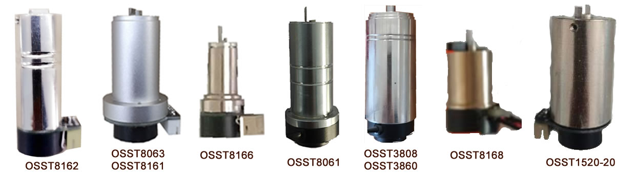
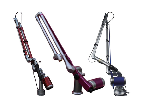
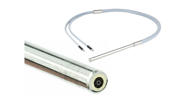
The galvanometer system is a high-precision and high-speed servo control system composed of a driving board, galvo and scan mirror, mainly used for laser marking, laser engraving, stage lighting control, etc.
The working principle of this system is that by inputting a position signal, the oscillating motor (galvanometer) will swing a certain angle according to a certain voltage and angle conversion ratio. The entire process adopts closed-loop feedback control, which is jointly operated by five control circuits/parts: position sensor, error amplifier, power amplifier, position discriminator, and current integrator.
The OSST series galvanometer systems produced by our company utilize the latest generation of integrated circuits and adopts various anti-interference methods to drive the circuit board. The system not only has strong anti-interference ability, high reliability, good linearity, high repetition accuracy, short response time, but also has a small size, which is easy to install and transport.
| Part number | OSST8162 | OSST8161 | OSST8063 |
| Optical apertures supported, two-axis | ≦8mm beam | ≦10mm beam | ≦12mm beam |
| Small-step response time | 0.2ms@5mm beam | 0.3ms@10mm beam | 0.6ms@12mm beam |
| Max mechanical rotation angle | ±20°-30 ° | ±20° | ±20° |
| Linearity | 99.9% @±20° | 99.9%@±20° | 99.9%@±20° |
| Peak current | 5A | 5A | 10A |
| Coil resistance | 3Ω±10% | 1.8Ω±10% | 2Ω±10% |
| Coil inductance | 180μH ±10% | 280μH ±10% | 260μH ±10% |
| Operation temp | 0℃-40℃ | 0℃-40℃ | 0℃-40℃ |
| Operation temp. (option) | -40—﹢85 | -40—﹢85 | -40—﹢85 |
| Weight | 80g | 105g | 180g |
| Rotor inertia | 0.125g·cm2 | 0.34g·cm2 | 1.2g·cm2 |
| Torque constant | 5.1N·mm/A | 7.3N·mm/A | 12 N·mm/A |
| Max. RMS current | 2.1A | 2.5 5A | 3.52A |
| Weight with cable | 72g | 263 g | 340g |
| Connector | C3030F-2*4 | C3030F-2*4 | C3030F-2*4 |
| Loading inertia | 0.1 g·cm2—0.54 g·cm2 | 0.3 g·cm2—1.52 g·cm2 | 1.0 g·cm2—6 g·cm2 |
| Following error | 0.11 ms | 0.142ms | 0.22 ms |
| Dimension | D15x31+D15.4x11mm | D22X36+D31x8.6+D21x9mm | D22x36+D31x8.6+D21x9mm |
| Mirror thickness | 2.1mm | 2.1mm | 2.1mm |
| Application | Stage lighting, laser animation | Ultra high speed flying marking, ultra high speed online rapid marking | Ultra high-speed flying marking, ultra high-speed online rapid marking metal, non-metallic precision laser marking, laser rapid prototyping, laser resistance adjustment and laser radar, etc |
| Part number | OSST8166 | OSST8168 | OSST8061 |
| Optical apertures supported, two-axis | 1-6mm beam | 1-10mm beam | 20-25mm beam |
| Small-step response time | 0.3ms@5mm beam | 0.3ms@5mm beam | 0.7ms@20mm beam |
| Max mechanical rotation angle | ±20° | ±20° | ±20° |
| Linearity | 99.9%@ ±20° | 99.9%@±20° | 99.9%@ ±20° |
| Peak current | 1.5A | 1.5A | 6A |
| Coil resistance | 2.3Ω±10% | 2.3Ω±10% | 2.1Ω±10% |
| Coil inductance | 420μH ±10% | 420μH ±10% | 360μH ±10% |
| Operation temp | 0℃-40℃ | 0℃-40℃ | 0℃-40℃ |
| Operation temp. (option) | -40—﹢85 | -40—﹢85 | -40—﹢85 |
| Weight | 26g | 26g | 210g |
| Rotor inertia | 0.028g·cm | 2.25N·mm/A | 5.1g·cm2 |
| Torque constant | 2.25N·mm/A | 2.25N·mm/A | 22N·mm/A |
| Max. RMS current | 1.8A | 1.8A | 5A |
| Weight with cable | 49 g | 425 g | |
| Connector | C3030F-2*4 | PHD2*4 | C3030F-2*4 |
| Loading inertia | 0.02 g·cm2—0.05 g·cm2 | 0.02 g·cm2—0.05 g·cm2 | 8 g·cm2—24 g·cm2 |
| Following error | 0.11 ms | 0.15 ms | 0.35 ms |
| Dimension | D10x16+D13x3+D15x10.5mm | D15X8+D14x15 | D28x58+D36x15+D25x5mm |
| Mirror thickness | 1.0mm | 1.mm | 3.0mm |
| Application | High speed online flying marking, high-speed high-precision static marking, etc | High speed online flying marking, high-speed high-precision static marking, etc | Precision laser marking, laser rapid prototyping, laser resistance modulation, laser radar, etc |
| Part number | OSST3808 | OSST3860 |
| Optical apertures supported, two-axis | 25-50mm beam | 30-60mm beam |
| Small-step response time | 1.2ms@25mm beam | 1.3ms@30mm beam |
| Max mechanical rotation angle | ±20° | ±20° |
| Linearity | 99.9%@±20° | 99.9%@±20° |
| Peak current | 7.6A | 9.6A |
| Coil resistance | 2Ω±10% | 2Ω±10% |
| Coil inductance | 260μH ±10% | 260μH ±10% |
| Operation temp | 0℃-40℃ | 0℃-40℃ |
| Operation temp. (option) | -40—﹢85 | -40—﹢85 |
| Weight | 520g | 520g |
| Rotor inertia | 6.25g·cm2 | 8.2g·cm2 |
| Torque constant | 28N·mm/A | 31·mm/A |
| Max. RMS current | 6.3 A | 12A |
| Weight with cable | 520G | 520G |
| Connector | C3030F-2*4 | C3030F-2*4 |
| Loading inertia | 12g·cm2—24 g·cm2 | 12g·cm2—35 g·cm2 |
| Following error | 0.28 ms | 0.35 ms |
| Dimension | D38X76+D36x5+D25x5mm | D38x76+D35x5+D25x5mm |
| Mount dia. Of the mirror | 7mm | 7mm |
| Application | Precision laser marking, laser rapid prototyping, laser resistance modulation, laser radar, etc | Precision laser marking, laser rapid prototyping, laser resistance modulation, laser radar, etc |
| Part number | OSST1520-20 | OSST1520-15 |
| Optical apertures supported, two-axis | ≦10mm beam | ≦10mm beam |
| Small-step response time | 0.3ms@10mm beam | 0.3ms@10mm beam |
| Max mechanical rotation angle | ±20° | ±20° |
| Linearity | 99.9%@±20° | 99.9%@±20° |
| Peak current | 5A | 5A |
| Coil resistance | 1.62Ω±10% | 1.8Ω±10% |
| Coil inductance | 103μH ±10% | 280μH ±10% |
| Operation temp | 0℃-40℃ | 0℃-40℃ |
| Operation temp. (option) | -40—﹢85 | ---- |
| Weight | 105g | 33g |
| Rotor inertia | 0.34g·cm2 | 0.34g·cm2 |
| Torque constant | 7.5N·mm/A | 7.5N·mm/A |
| Max. RMS current | 2.5 A | 2.5 A |
| Weight with cable | 263 g | Socket |
| Connector | PHD2*4 | PHD2*4 |
| Loading inertia | 0.35 —1.5 g·cm2 | 0.35 —1.5 g·cm2 |
| Following error | 0.15 ms | 0.15 ms |
| Dimension | D20X26+D15x11mm/37mm | D15X26+D15x11mm/37mm |
| Mirror thickness | 2.0mm (to be stuck) | 2.0mm(to be stuck) |
| Application | Ultra high speed flying marking, ultra high speed online rapid marking | Ultra high speed flying marking, ultra high speed online rapid marking |
Remarks:
All the galvos are chrome coated cover.
The scan mirrors at the laser wavelengths of 1064nm, 532nm, 355nm, 266nm, 10.6um and others are available upon request.
There are 2 types of drive boards for OSST series galvos: one board to drive 2 galvos (1-to-2 board or just called board, default); one board to drive 1 galvo (1-to-1 board). Their driving capabilities and main performance are same. The main difference is the dimension.
General specifications:
Supply power: ±15VDC to ±24VDC
Analog input position signal: ±5V (default), ±10V available upon requestion.
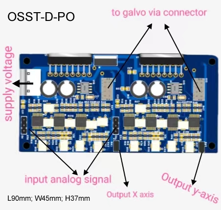
Position signal output (option): 1:1 port and 1:10 port.
1. 1-to-2 Boards
1.1 1-to-2 Board without Position Output Signal (OSST-D)
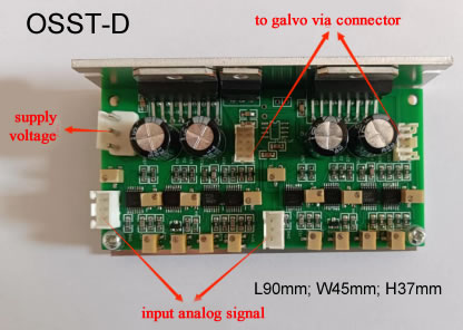
This driver is mostly used in 2D laser marking/scanning.
1.2 1-to-2 Board with Position Signal Output (OSST-D-PO)
2. 1-to-1 Boards
1-to-2 Board with Position Signal Output (OSST-D-1-PO)
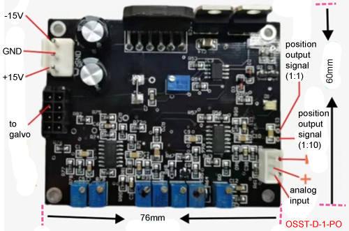
There are 2 position signal outputs for use.
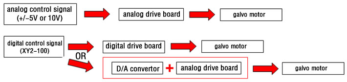
Depending the required control signal of the drive boards and the control signal of your control system, a D/A card may be needed.
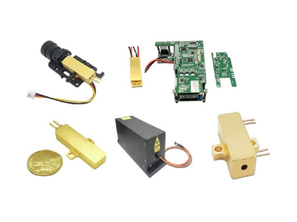
A leading supplier and manufacturer of a wide range of photonics products such as lasers,laser parts & machines.
Office: 18 South Liu Fang Yuan Road, Sintec Industrial Park, Optics Valley of China, Wuhan Hubei, 430205 PR China
Tel: +86 27 51858962
Fax: +86 27 51858989
Whatsapp: 15671598018
E-mail: info@SintecLaser.com